

CREATE NEW BAND STYLE IN AUTOCAD CIVIL 3D
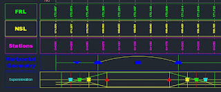
Bands mean Table of FRL, PGL, NSL, NGL, Stations, RD’s
etc.
i.
Select Graph, profile, boundary, surface etc and
Right Click
ii.
Profile view properties
iii.
Enter name Design Level, Natural Ground Level,
Station etc
iv.
Stations see first and last station or RD
v.
Elevation see minimum and maximum elevation (
can change this)
vi.
Profiles ( see surface name and profile name
should be here)
vii.
And then Bands
viii.
Select already appeared band
ix.
Delete this band ( for delete select the band
and click on red X right middle under arrows)
x.
Apply and Ok ( already c3d self created band
should be deleted)
xi.
Now select the graph and right click
xii.
Profile view properties
xiii.
Bands
xiv.
Select Band style
xv.
Click on Icon’s arrow in front of cut data
xvi.
From drop down menu click at create new
xvii.
Profile data band style ( window open)
xviii.
Information Name (xyz etc) such as Design Level
xix.
Band details
xx.
Title text (Compose label)
xxi.
Anchor Point
change to Middle center (In properties General)
xxii.
Attachment change to Middle center (in Text)
xxiii.
Contents profile data click at (…)
xxiv.
Text profile data will be shown in the view
xxv.
Delete this text and re enter the text Design
level or Natural Ground Level or Station
xxvi.
Ok and OK
xxvii.
Return to the profile view properties (window)
xxviii.
Labels and Ticks
xxix.
Major station checked the Top and Bottom options
and change the both tick size
xxx.
xxxi.
Label style composer- major station (window will
open)
xxxii.
Click at red (X) and delete station value
xxxiii.
Profile 1 Elevation will be appeared at the
place of station value
xxxiv.
General – Name- Design level, Natural Ground
Level etc
xxxv.
TEXT- Attachment change to Middle center
xxxvi.
Text height 2mm, 3mm, 4mm etc
xxxvii.
Contents (profile 1 elevation) click at (…)
xxxviii.
New window will open text component editor
xxxix.
Select
the whole text which shown in the view
xl.
And change the precision to 0.01, 0.001. 0.000
etc
xli.
Then click under properties and click at profile
1 elevation
xlii.
From drop down menu select profile 2 elevation
xliii.
And change the precision 0.01,0.001,0.000 etc
xliv.
Then click on arrow in front of properties
profile 2 elevation
xlv.
Ok and OK ( Return to profile data band style
window)
xlvi.
Labels and Ticks At:
xlvii.
Minor Station ( Unchecked or deselect top and
bottom)
xlviii.
Click at compose label
xlix.
Click at red (X) 2 time and delete station
elevation and profile 1 elevation
l.
Same above 3 steps for horizontal geometry point
and vertical geometry point
li.
Select Station Equation and unchecked the top
and bottom
lii.
Remember here will not click at compose label
liii.
OK
liv.
Then click at ADD>> icon
lv.
After add the band into the table change
profile1 and Profile2 to Design ( it is just for FRL,PGL Band not for Ground or NSL or Station bands)
lvi.
Same process for other bands which we need to
ADD just change name of the Band but lick Design level band in other bands
profile1 and profile2 will not change, it will be same it is.
lvii.
For station or RD
lviii.
lix.
Create new
lx.
Station (Name)
lxi.
Band Details
lxii.
Compose labels
lxiii.
Station (Name)
lxiv.
Anchor Point change to Middle center
lxv.
Text Attachment change to Middle Center
lxvi.
Text Height 2mm,3mm etc
lxvii.
Contents click at (…) icon
lxviii.
Delete text profile data and re enter the text
STATION
lxix.
Labels and tick AT:
lxx.
Same as above created bands,
lxxi.
But here
delete profile 1 elevation
lxxii.
Station value will not be deleted
lxxiii.
ADD>>
lxxiv.
Apply and OK
lxxv.
The Design Elevation, Ground Elevation or NSL
and Stations should be attached with the graph.
lxxvi.
We can change the gap between the bands and size
of bands to right click at any band
lxxvii.
Edit band style
lxxviii.
Layout etc
lxxix.
In the profile view properties can change the
gap between the bands
lxxx.
Click at Gap in the front of Band name
lxxxi. OK
TO DOWNLOAD THE CIVIL 3D FILE CLICK AT THE DOWNLOAD BUTTON.


0 Comments